A week ago or so I started learning the ISTQB glossary to familiarize with the official nomenclature. I use the Polish/English bilingual version (3.4) available on SJSI page. Of course, I also recommend the official glossary website. As my main learning tool is Anki, I created a new deck and I enter several new terms every day, according to the small step method known from Kaizen methodology. Some of the terms are quite simple, other require further studying. By this post, I introduce the new series devoted to some more complicated (or simply more interesting) concepts from the ISTQB glossary.
The first term I would like to describe is the cause-effect diagram known as Ishikawa diagram. Let’s review the definition by ISTQB:
- Cause-effect diagram
- A graphical representation used to organize and display the interrelationships of various possible root causes of a problem. Possible causes of a real or potential defect or failure are organized in categories and subcategories in a horizontal tree-structure, with the (potential) defect or failure as the root node.
The idea of Ishikawa diagrams (also called fishbone diagrams) was created by Kaoru Ishikawa, a Japanese quality specialist, in the 1960’s. The method is useful in searching for individual root causes of a defect or problem. At first, we define our problem and then, through brainstorming, we search for more general reasons, e.g. using a 5M+E model (although other models are also used), i.e. focusing on the following areas:
- Manpower
- Machine
- Material
- Method
- Management
- Environment
Of course, you can select other areas more suitable for the individual situation – please see Techtarget article where the following areas were selected to find causes of a drop in an app usage:
- Marketing
- Support
- Infrastructure
- Trends
- Usability
- Competition
For each of the areas, we try to find potential general causes. After that, each general cause can be further brainstormed to spot individual root causes contributing to them. This way we can gradually obtain a comprehensive list of potential root causes which can be really useful in troubleshooting a problem. The whole list is depicted on a horizontal diagram resembling a fish skeleton.
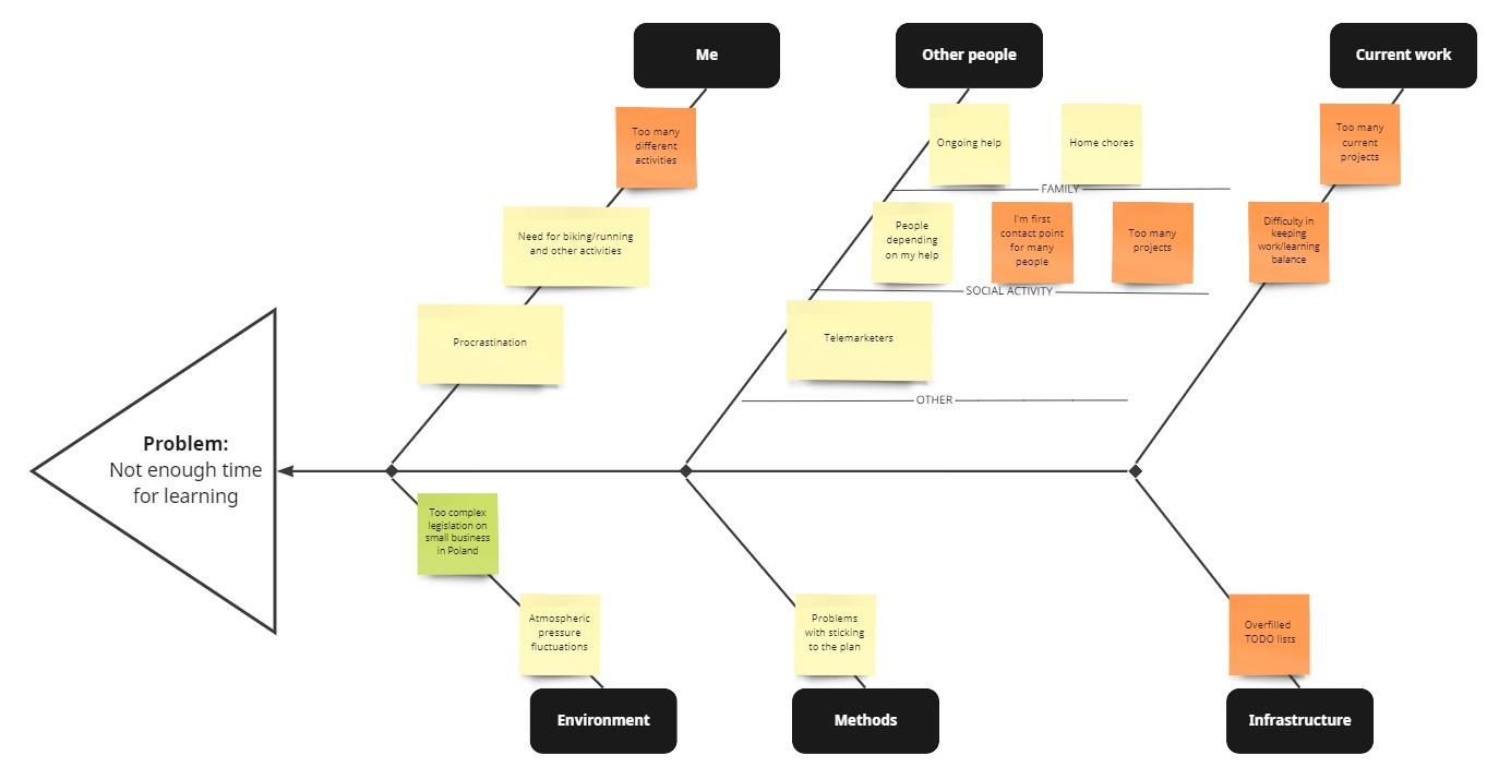
To practise the method, I created an exemplary diagram using Miro platform, as I wanted to check the tool at the same time. The platform offers easy-to-use creators and templates which guide through the processes and really speed up the whole brainstorming. At the same time, I tried to discover why sometimes I have too little time for learning. The options offered by Miro allowed me to highlight some of the most important root causes. Now, I can proceed to improving the selected factors.
I would recommend the following further reading: